Minggu, 25 Mei 2014

Chapter 13 : Computer Numerical Control

Figure 13.1 CNC Machine

      Computer Numerical Control (CNC) is one in which the functions and motions of a machine tool are controlled by means of a prepared program containing coded alphanumeric data. CNC can control the motions of the workpiece or tool, the input parameters such as feed, depth of cut, speed, and the functions such as turning spindle on/off, turning coolant on/off. The applications of CNC include both for machine tool as well as non-machine tool areas. In the machine tool category, CNC is widely used for lathe, drill press, milling machine, grinding unit, laser, sheet-metal press working machine, tube bending machine, etc. Highly automated machine tools such as turning center and machining center which can change the cutting tools automatically under CNC control have been developed. In the non-machine tool category, CNC applications include welding machines (arc and resistance), coordinate measuring machine, electronic assembly, tape laying and filament winding machines for composites, etc. There are three basic components of CNC System, such as : Part program, Machine Control Unit (MCU), and machine tool ( lathe,drill press, milling machine, etc).
       Advantages  and disadvantages of CNC :
  1. High accuracy in manufacturing
  2. Short production time
  3. Greater manufacturing flexibility
  4. Simpler Fixturing
  5. Contour Machining ( 2 to 5-axis machining)
  6. Reduced Human Error
      And the drawbacks include high cost, maintenance, and the requirement of skilled part programmer.

Source :
http://wings.buffalo.edu/academic/department/eng/mae/courses/460-564/Course-Notes/CNC%20notes.pdf

Chapter 12 : Programmable Control Logic

     
Figure 12.1 PLCs
  A Programmable Logic Controller is a digital computer used for automation of electromechanichal processess, such as control of machinery on factory assembly lines, control of amusement rides. It uses programmable memory to store instructions and the specific functions that include ON/OFF control, timing counting, sequencing, arithmatic, and data handling. Programmable logic employs electronic processing units in order to process data. The operation of equipment constructed according to this technique is not defined by a circuit diagram, as for that used in hard wired logic, but by a program loaded into the memory of the processing unit. Programmable logic controllers are the basic components used in electronic automated systems and first appeared in the United states in 1969. Today, numerous models of programmable controller are available, from small PLCs suited to dimple applications and installations with a few inputs/outputs, up to multifunction PLCs capable of controlling several thousands of inputs/outputs and designed to control complex processes. The main difference from other computer is that PLCs are armored for severe conditions (dust, moisture, heat, cold, etc) and have the facility for extensive input/output (I/O) arrangements. Another advantages of PLC are : Cost effective for controlling complex systems. Flexible and can be reapplied to control other systems quickly and easy, and allow more sophisticated control because of the computational abilities. The disadvantages of PLC are : Too much work required in connecting wires and difficulty with changes or replacements.
Figure 12.2 Applications of PLC


Source :
http://me.emu.edu.tr/majid/IENG447/IE%20447/PLC%20ppt.pdf

Rabu, 14 Mei 2014

Chapter 11 : Types of processes in process control system

              The types of processes carried out in modern manufacturing industries can be grouped into three general areas, in terms of the kind of operation that takes place, as :

  • Continous process
  • Batch production
  • Individual products production               

            A continous process is one in which raw materials enter one end of the system and the finished product comes out the other end of the system : the process itself runs continously. Once the process commences, it is continous for a relatively long period of time. The time period may be measured in minutes, days, or even months, depending upon the process. In batch processing, there is no flow of product material from one section of the process to another. Instead, a set amount of each of the inputs to the process is received in a batch, and then some operations is performed on the batch to produce a finished product or  an intermediate product that needs further processing. The process is carried out, the finished product is stored, and another batch of product is produced. Each batch of product may be different. Some processes combine the features of the batch and continous types. In such processes, several product materials are treated and stored in batch operation. Then these stored materials are drawn off as required into a continous process. Many chemically based products are manufactured by using batch processes. Two ingrediets are added together, mixed, heated, a third ingredient is added, processed, and then stored. Each batch made may have differing characteristics by design. 
        The individual product production process is the most common of all processing of all processing systems. With this manufacturing process, a series of operations produces a useful output product. The item being produced may be required to be bent, drilled, welded, and so on, at different steps in the process. The workpiece is normally a discrete part that must be handled on an individual basis. In the modern automated industrial plant, the operator merely sets up the operation and initiates a start, and the operations of the machine are accomplished automatically. These automatic machines and processes were developed to mass-produce products, control very complex operations, or to operate machines accurately for long periods of time. They replaced much human decision, intervention, and observation.
        Machines were originally mechanically controlled, they were electromechanically controlled, and today they are often controlled by purely electrical or electronic means through programmable logic controllers (PLCs) or computers. The control of machines or processes can be divided into the folllowing categories :
  1. Electromechanical control
  2. Hardwired electronic control
  3. Programmable hardwire electronic control
  4. Programmable logic control (PLC)
  5. Computer control
Source :

Petruzella, Frank. (1995). Industrial Electronics. Mc Graw Hill.304-305

Chapter 10 : Count Control

                                                                       Figure 10.1 Counters
       Counters are devices that will receive a string of count pulses from a machine operation and perform an output function based on a number of counts predetermined by the user. Most counters, like timers, can have interval and delay operation. Interval operation means that a load will be actuated when the unit is counting. Delay operation means that a load will be actuated at the end of the counting cycle. Solid-state and electromechanical versions are available.
         Counters are generally thought of as devices that tabulate or count "things" such as bottles, cans, boxes, castings, and so on. In many industrial control systems, it is necessary to count something that affects a controlled process. When the count reaches a certain number, a control action is initiated. In a mechanical counter, every time the actuating lever is moved over, the counter adds one number, and the actuating lever returns automatically to its original position. Resetting to zero is done by a pushbutton located on the side of the unit. In an electromechanical counter, the count setpoint can be adjusted by the knob on the front of the unit. A progress pointer, indicating the count progression, advances clockwise, from setpoint to zero. A solid-state counter has high speed pulse operation with 100 percent accuracy and has may programmable features. Counter output action occurs when the count total indicated by the thumbwheel switches is reached.
 (a) Electromechanical Counter
(b) Mechanical Counter

(c) Solid-State Counter

10.2 Types of Counters used
     
The circuit of counters operates as follows :
  • The sustained control switch is closed to energize clutch and enable the counter to- receive and register counts
  • Instantaneous contacts transfer
  • Each time the count switch is momentarily closed, a pulse is applied to the cout motor to register a count by moving the count progress pointer toward the zero point on the dial
  • When the progress poiter reaches zero, the unit is counted out and the delay switch operates to turn output A ON and output B OFF
  • Additional counts will not be registered until the unit is reset
  • Opening the control switch to remove power from the clutch resets the counter
     Most solid-state counters can count up, count down, or be combined to count up and down. An up-counter will count up or increment by 1 each time the counted event occurs. A down-couter will count down or decrement by 1 each time the the counted event occurs. Normally the down-counter is used in conjuntion with the up-counter to form an up/down-counter equipped with separate count-up and count-down inputs.


Source :

Petruzella, Frank. (1995). Industrial Electronics. Mc Graw Hill.291-293

Chapter 9 : Motor Reversing

Figure 9.1 Three-phase reversing starter
                     A three-phase reversing starter consists of two contactors enclosed in the same cabinet. As seen in the power circuit, the contacts (F) of the forward contractor, when closed, connect L1, L2, and L3 to motor terminals T1,T2, AND T3, respectively. The contacts (R) of the reverse contactor, when closed, connect L1 to motor terminal T3 and connect L3 to motor terminal T1, causing the motor run in the opposite direction. Mechanical and electrical interlocks are used to prevent the forward and reverse contactors from being activated at the same time, which would cause a short circuit.

                                                              (a) Mechanical Interlock


(b) Electrical Pushbutton Interlock

                                           (c) Electrical Auxiliary Contact Interlock
                        Figure 9.2 Reversing starter mechanical and electrical interlocks
           With the mechanical interlock, the first coil to close moves a lever to a position that prevents the other coil from closing its contacts when it is energized. Electrical pushbutton interlocks use double-contact ( NO and NC) pushbuttons. When the forward pushbutton is pressed, the NC contacts open the reverse-coil circuit. There is no need to press the STOP button before changing the direction of rotation. If the forward button is pressed while the motor is running in the reverse, direction, the reverse control circuit is deenergized and the forward contactor is energized and held closed. The reversal of a dc motor can be accomplished in two ways :
  1. Reversing the direction of the armature current ad leaving the field current the same
  2. Reversing  the direction of the field current and leaving the armature current the sameca
        Most DC motors are reversed by sitching the direction of current flow through the armature. The switching action generally takes place in the armature because the armature has a much lower inductance than the field. The lower inductance causes less arcing of the switching contacts when the motor reverse its direction.

Source :
Petruzella, Frank. (1995). Industrial Electronics. Mc Graw Hill.251-253


Selasa, 13 Mei 2014

Chapter 8 : Magnetic Contactor

      The National Electrical Manufactures Association (NEMA) defines a magnetic contactor as a magnetically actuated device for repeatedly establishing or interrupting an electric power circuit. Unlike relays, contactors are designed to make and break electric power circuits without being damaged.
Figure 8.1 Magnetic Contactors

      A contactor has three components. The contacts are the current carrying part of the contactor. This includes power contacts, auxiliary contacts, and contact springs. The electromagnet (or "coil") provides the driving force to close the contacts. The enclosure is a frame housing the contact and the electromagnet. Enclosures are made of insulating materials to protect and insulate the contacts and to provide some measure of protection against personnel touching the contacts. Open-frame contactors may have a further enclosure to protect against dust, oil, explosion hazards and weather.

     The advantages of using magnetic contactors instead of manually operated control equipment include the following :
  1. Where large currents or high voltages have to be handled, it is difficult to build a suitable manual apparatus. Furthermore, such an apparatus is large and hard to operate. On other, it is a relatively simple matter to build a magnetic contactor that will handle large current or high voltages and the manual apparatus must control only the coil of the contactor
  2. Contactors allow multiple operations to be performed from one operator (one location) and interlocked to prevent false and dangerous operations
  3. Where the operation must be repeated many times an hour, a distinct saving i effort will result if contactors are used. The operator simply has to push a button and the contactors will automatically initiate the proper sequence of events
      The principal parts of a magnetic contactor are the electromagnet and the contacts.  . The magnetic circuit consist of soft steel with high permeability and low residual magnetism. The magnetic pull developed by the coil must be sufficient to close the armature from being held in by residual magnetism, a permanent air gap must be provided in the magnetic circuit. This is generally accomplished by placing a shim of nonmagnetic material between the core and the supporting frame, under the core head or at the core face.
Types of magnetic Contactors :
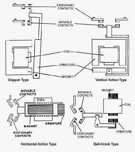
There are four basic types of electromagnetic contactors :

Figure 8.2 Magnetic contactors type
  • Clapper Type - It contains a hinged armature that pivots to seal in, thus closing the moveable contacts against the stationary contacts.
  • Horizontal Action - The armature and the contacts move horizontally in a straight line.
  • Vertical Action - The armature and contacts move in a straight vertical line.
  • Bell Crank - A bell crank converts the vertical movement of the armature into a horizontal motion. Longer contact life and reduced contact bounce result from lessened shock on armature pickup.

Source :
http://en.wikipedia.org/wiki/Contactor
http://ecmweb.com/content/basics-contactors
http://www.myodesie.com/index.php/wiki/index/returnEntry/id/2976
Petruzella, Frank. (1995). Industrial Electronics. Mc Graw Hill.216-218


Chapter 7 : Electromechanical Control Relays

Figure 7.1 Electromechanical Relay (EMR)

       Electromechanical Relay ( EMR) is a magnetic switch. It turns a load circuit ON or OFF by energizing an electromagnet, which opens or closes contacts in both electric and electronic circuits. EMRs may be used in the control of fluid power valves and in many machine sequence controls such as drilling, boring, milling, and grinding operations. A relay will usually have only one coil,  but it may have any number of different contacts. Electromechanical relays contain both stationary and moving contacts.The moving contacts are attached to the plunger. Contacts are referred to as normally open (NO) and normally closed (NC).
Figure 7.2 Parts of Electromechanical relay

Basic parts and functions of electromechanical relays include: 
  1. Frame: Heavy-duty frame that contains and supports the parts of the relay.
  2. Coil: Wire is wound around a metal core. The coil of wire causes an electromagnetic field.
  3. Armature: A relays moving part. The armature opens and closes the contacts. An attached spring returns the armature to its original position.
  4. Contacts: The conducting part of the switch that makes (closes) or breaks (opens) a circuit
Figure 7.3 Mechanical operation of Electromechanical relay

      When the coil is energized, it produces an electromagnetic field. Action of this field, in turn, causes the plunger to move through the coil, closing the NO contacts and opening the NC contacts. Normally open contacts are open when no current flows through the coil but closed as soon as the coil conducts a current or is energized. Normally closed contacts are closed when the coil is deenergized and open when the coil is energized. Each contact is usually drawn as it would appear with the coil deenergized. Most machine control relays have some provision for changing contacts normally open to a normally closed, or vice versa. It ranges from a simple flip-over contact to removing the contacts and relocating with spring location changes.
        In general, control relays are used as auxiliary devices to switch control circuits and loads such as small motors, solenoids, and pilot light. The EMR can be used to control a high-voltage load circuit with a low-voltage control circuit. This is possible because the coil and contacts of the relay are electrically insulated from each other. From a safety point of view, this circuit provides extra protection for the operator. Another basic application for a relay is to control a high-current load circuit with a low-current control circuit.This is possible because the current that can be handled by the contacts can be much greater that what is required to  operate the coil. 

Sources :
http://www.galco.com/comp/prod/relay.htm
Petruzella, Frank. (1995). Industrial Electronics. Mc Graw Hill.202-204


Chapter 6 : Alternating Current Generators


                                                            Figure 6.1 AC generators

    An electric generator, or dynamo, is a device which converts mechanical energy into electrical energy. The simplest practical generator consists of a rectangular coil rotating in a uniform magnetic field. The magnetic field is usually supplied by a permanent magnet.

Figure 6.2 Left-hand generator rule

     This rule shows the relationship between the direction of the conductor is moving, the direction of the magnetic field, and the resultant direction of the induced current flow.When the thumb is pointed in the direction of the conductor's motion, and the index finger is pointed in the direction of the flux, the middle finger will point in the direction of the induced electron flow. The rule is also applicable when the magnet, instead of the conductor, is moved.
     There are 2 types of alternating current generators, they are Stationery Field Synchronous AC Generator and Rotating Field Synchronous AC Generator.
  1. Stationery Field Synchronous AC Generator 
In a stationary field generator, the stator in the form of fixed permanent magnets ( or electromagnets fed by DC) provides the magnetic field and the current is generated in the rotor windings. This type is usually of relatively small kilovolt-ampere capacity and low-voltage rating. It resembles a dc generator in appearence, except that it has slip rings instead of a commutator.
Figure 6.3 Stationary-field single-phase ac generator

    2.Revolving-Field three-phase AC Generator
          The revolving-type of ac generator simplifies the problems of insulating generated voltages, which are commonly as high as 18,000 to 24,000 VA revolving-field ac generator has a stationary armature called a stator. The three-phase stator winding is directly connected to the load without going through slip rings and brushes. The revolving-field ac generator uses a brushless exciter system in which a small ac generator mounted on the same shaft as the main generator is used as an exciter. The ac exciter has a rotating armature.The output of the armature is rectified by solid-states diodes, which are also mounted on the main shaft. The rectified output of the ac exciter is fed directly by means of insulated connections along the shaft to the rotating synchronous generator field. The field of the ac exciter is stationart and is supplied from a separate dc source

Sources :

http://farside.ph.utexas.edu/teaching/302l/lectures/node90.html
Petruzella, Frank. (1995). Industrial Electronics. Mc Graw Hill.172-173

Minggu, 11 Mei 2014

Chapter 5 : Phototransistors

     
Figure 5.1 Phototransistors

        Phototransistors is a semiconductor device that converts light into currentA phototransistor is in essence nothing more than a bipolar transistor that is encased in a transparent case, so that light can reach the base-collector junction.The phototransistor works like a photodiode, but with a much higher sensitivity for light, because the electrons that are generated by photons in the base-collector junction are injected into the base, and this current is then amplified by the transistor operation.However, a phototransistor has a slower response time than a photodiode.

Figure 5.2 Phototransistors scheme

        Based on the scheme at the photo current, the electrons are amplified by the transistor and appear as a current in the collector/emitter circuit. The base is internally left open and is at the focus of a plastic lens.The actual operation of a phototransistor depends on the biasing arrangement and light frequency. For instance, if a PN junction is forward biased, the increased current through the junctions due to incident light will be relatively insignificant. On the other hand, if the same junction is reverse biased, the increase in current flow will be considerable and is a function of the light intensity. Therefore, reverse bias is the normal mode of operation.

Figure5.3 Phototransistor operation

           Now, if the PN junction is the collector-base diode of a bipolar transistor, the light-induced current effectively replaces the base current. The physical base lead of the transistor can be left as an open terminal, or it can be used to bias up to a steady state level. It is the nature of transistors that a change in base current can cause a significant change (increase) in collor current. Thus, light stimulation causes a change in base current, which in turn causes a bigger increase in collector current and, considering the current gain (hfe), a rather large increase at that.
            Phototransistors have several important advantages that separate them from other optical sensors. For example, phototransistors produce a higher current than photodiodes while also being able to produce a voltage, something that photoresistors cannot do. Phototransistors are very fast and are capable of providing nearly instantaneous output. Phototransistors are relatively inexpensive, simple, and small enough to fit several of them onto a single integrated computer chip. While phototransistors can be advantageous, they also have several disadvantages. For example, phototransistors made of silicon are not capable of handling voltages over 1,000 Volts. Phototransistors also do not allow electrons to move as freely as other devices do, such as electron tubes. Phototransistors are also more vulnerable to surges and spikes of electricity as well as electromagnetic energy.
Sources :
Petruzella, Frank. (1995). Industrial Electronics. Mc Graw Hill.1-2
http://theonlinetutorials.com/what-is-a-phototransistor-and-how-it-works.html
http://en.wikipedia.org/wiki/Photodiode


Chapter 4 : Push-button switch

       A push-button is a simple switch mechanism for controlling some aspect of a machine or a process. Buttons are typically made out of hard material, usually plastic or metal. The surface is usually flat or shaped to accomodate the human finger or hand, so as to be easily depressed or pushed. 
       Most push button switches are also known as biased switches. A biased switch, can be also considered what we call a "momentary switch" where the user will push-for "on" or push -for "off" type. This is also known as a push-to-make (SPST Momentary) or push-to break (SPST Momentary) mechanism.
       Switches with the "push-to-make"(normally-open or NO) mechanism are a type of push button electrical switch that operates by the switch making contact with the electronic system when the button is pressed and breaks the current process when the button is released. An example of this is a keyboard button. A "push-to-break" (or normally-closed or NC) electronic switch, on the other hand, breaks contact when the button is pressed and makes contact when it is released.

Figure 4.1 : Example of push-button switch

In industrial and commercial applications, push buttons can be connected together by a mechanical linkage so that the act of pushing one button causes the other button to be released. In this way, a stop button can "force" a start button to be released. This method of linkage is used in simple manual operations in which the machine or process have no electrical circuit or control.
Pushbuttons are often color-coded to associate them with their function so that the operator will not push the wrong button in error. Commonly used colors are red for stopping the machine or process and green for starting the machine or process.
Red pushbuttons can also have large heads (called mushroom heads) for easy operation and to facilitate the stopping of a machine. These pushbuttons are called emergency stop buttons and are mandated by the electrical code in many jurisdictions for increased safety. This large mushroom shape can also be found in buttons for use with operators who need to wear gloves for their work and could not actuate a regular flush-mounted push button. As an aid for operators and users in industrial or commercial applications, a pilot lights is commonly added to draw the attention of the user and to provide feedback if the button is pushed. 
Figure 4.2 Internal views of pushbutton switches

Sources :
http://en.wikipedia.org/wiki/Push-button
http://www.futureelectronics.com/en/switches/push-button-switches.aspx
http://shpat.com/docs/grayhill/pushbuttons.pdf

Chapter 3 : Three-Phase Transformer Systems

Three-phase electric power is a common method of alternating-current electric power generation, transmission, and distribution. It is a type of polyphase system and is the most common method used by electrical grids worldwide to transfer power. It also used to power large motors and other heavy loads. A three-phase sy stem is usually more economical than an equivalent or two-phase system at the same voltage because it uses less conductor material to transmit electrical power.There are two basic three-phase configurations: delta and wye (star). Either type can be wired for three or four wires. The fourth wire, if present, is provided as a neutral. The '3-wire' and '4-wire' designations do not count the ground wire used on many transmission lines which is solely for fault protection and does not carry curr to transferent under non-fault conditions.
Figure 3.1 Wye (Y) and Delta (Δ) circuits
For practical calculations, it is reasonable to model the three-phase transformer as three ideal transformers as shown in Figure 2 below. Since these transformers are ideal, the secondary voltages are related to the primary voltages by the turns ratio according to :
                                     Figure 3.2 Three-phase transformer ideal model

There are 4 kinds relations of  three-phase transformer systems, such as :
  1. Wye-Delta: Commonly used in a step-down transformer, wyeconnection on the HV side reduces insulation costs,the neutral point on the HV side can be grounded,stable with respect to unbalanced loads.
  2. Delta-Wye: Commonly used in a step-up transformer for thesame reasons as above.
  3. Delta-Delta: Offers the advantage that one of the transformers can be removed while the remaining two transformers can deliver three-phase power at 58% of the original bank.
  4. Wye-Wye: Rarely used, problems with unbalanced loads.
Sources :
http://www.ece.msstate.edu/~donohoe/ece3614three_phase_transformers.pdf
http://ece.mst.edu/media/academic/ece/documents/classexp/ee208labs/04_-_Three-Phase_Transformers.pdf
http://opencourseware.kfupm.edu.sa/colleges/ces/ee/ee360/files%5C3-Lesson_Notes_Lec_11_3_phase_traqnsformers.pdf

Chapter 2 : Ladder Diagram


Ladder diagrams are specialized schematics commonly used to document industrial control logic systems. They are called "ladder" diagrams because they resemble a ladder, with two vertical rails (supply power) and as many "rungs" (horizontal lines) as there are control circuits to represent. If we wanted to draw a simple ladder diagram showing a lamp that is controlled by a hand switch, it would look like this:
                                             Figure 2.1 Simple ladder diagram


The "L1" and "L2" designations refer to the two poles of a 120 VAC supply, unless otherwise noted. L1 is the "hot" conductor, and L2 is the grounded ("neutral") conductor. These designations have nothing to do with inductors, just to make things confusing. The actual transformer or generator supplying power to this circuit is omitted for simplicity. In reality, the circuit looks something like this: 
                                           Figure 2.2 Actual ladder diagram circuit
The language itself can be seen as a set of connections between logical checkers (contacts) and actuators (coils). If a path can be traced between the left side of the rung and the output, through asserted (true or "closed") contacts, the rung is true and the output coil storage bit is asserted (1) or true. If no path can be traced, then the output is false (0) and the "coil" by analogy to electromechanical relays is considered "de-energized"..
Ladder logic has contacts that make or break circuits to control coils. Each coil or contact corresponds to the status of a single bit in the programmable controller's memory. Unlike electromechanical relays, a ladder program can refer any number of times to the status of a single bit, equivalent to a relay with an indefinitely large number of contacts.
So-called "contacts" may refer to physical ("hard") inputs to the programmable controller from physical devices such as pushbuttons and limit switches via an integrated or external input module, or may represent the status of internal storage bits which may be generated elsewhere in the program.
Each rung of ladder language typically has one coil at the far right. Some manufacturers may allow more than one output coil on a rung.
·         —( )— A regular coil, energized whenever its rung is closed.
·         —(\)— A "not" coil, energized whenever its rung is open.
·      —[ ]— A regular contact, closed whenever its corresponding coil or an input which controls it is energized.
·    —[\]— A "not" contact, closed whenever its corresponding coil or an input which controls it is not energized.

Sources :
Petruzella, Frank. (1995). Industrial Electronics. Mc Graw Hill.1-2
http://www.allaboutcircuits.com/vol_4/chpt_6/1.html