Selasa, 13 Mei 2014

Chapter 6 : Alternating Current Generators


                                                            Figure 6.1 AC generators

    An electric generator, or dynamo, is a device which converts mechanical energy into electrical energy. The simplest practical generator consists of a rectangular coil rotating in a uniform magnetic field. The magnetic field is usually supplied by a permanent magnet.

Figure 6.2 Left-hand generator rule

     This rule shows the relationship between the direction of the conductor is moving, the direction of the magnetic field, and the resultant direction of the induced current flow.When the thumb is pointed in the direction of the conductor's motion, and the index finger is pointed in the direction of the flux, the middle finger will point in the direction of the induced electron flow. The rule is also applicable when the magnet, instead of the conductor, is moved.
     There are 2 types of alternating current generators, they are Stationery Field Synchronous AC Generator and Rotating Field Synchronous AC Generator.
  1. Stationery Field Synchronous AC Generator 
In a stationary field generator, the stator in the form of fixed permanent magnets ( or electromagnets fed by DC) provides the magnetic field and the current is generated in the rotor windings. This type is usually of relatively small kilovolt-ampere capacity and low-voltage rating. It resembles a dc generator in appearence, except that it has slip rings instead of a commutator.
Figure 6.3 Stationary-field single-phase ac generator

    2.Revolving-Field three-phase AC Generator
          The revolving-type of ac generator simplifies the problems of insulating generated voltages, which are commonly as high as 18,000 to 24,000 VA revolving-field ac generator has a stationary armature called a stator. The three-phase stator winding is directly connected to the load without going through slip rings and brushes. The revolving-field ac generator uses a brushless exciter system in which a small ac generator mounted on the same shaft as the main generator is used as an exciter. The ac exciter has a rotating armature.The output of the armature is rectified by solid-states diodes, which are also mounted on the main shaft. The rectified output of the ac exciter is fed directly by means of insulated connections along the shaft to the rotating synchronous generator field. The field of the ac exciter is stationart and is supplied from a separate dc source

Sources :

http://farside.ph.utexas.edu/teaching/302l/lectures/node90.html
Petruzella, Frank. (1995). Industrial Electronics. Mc Graw Hill.172-173

Minggu, 11 Mei 2014

Chapter 5 : Phototransistors

     
Figure 5.1 Phototransistors

        Phototransistors is a semiconductor device that converts light into current. A phototransistor is in essence nothing more than a bipolar transistor that is encased in a transparent case, so that light can reach the base-collector junction.The phototransistor works like a photodiode, but with a much higher sensitivity for light, because the electrons that are generated by photons in the base-collector junction are injected into the base, and this current is then amplified by the transistor operation.However, a phototransistor has a slower response time than a photodiode.

Figure 5.2 Phototransistors scheme

        Based on the scheme at the photo current, the electrons are amplified by the transistor and appear as a current in the collector/emitter circuit. The base is internally left open and is at the focus of a plastic lens.The actual operation of a phototransistor depends on the biasing arrangement and light frequency. For instance, if a PN junction is forward biased, the increased current through the junctions due to incident light will be relatively insignificant. On the other hand, if the same junction is reverse biased, the increase in current flow will be considerable and is a function of the light intensity. Therefore, reverse bias is the normal mode of operation.

Figure5.3 Phototransistor operation

           Now, if the PN junction is the collector-base diode of a bipolar transistor, the light-induced current effectively replaces the base current. The physical base lead of the transistor can be left as an open terminal, or it can be used to bias up to a steady state level. It is the nature of transistors that a change in base current can cause a significant change (increase) in collor current. Thus, light stimulation causes a change in base current, which in turn causes a bigger increase in collector current and, considering the current gain (hfe), a rather large increase at that.
            Phototransistors have several important advantages that separate them from other optical sensors. For example, phototransistors produce a higher current than photodiodes while also being able to produce a voltage, something that photoresistors cannot do. Phototransistors are very fast and are capable of providing nearly instantaneous output. Phototransistors are relatively inexpensive, simple, and small enough to fit several of them onto a single integrated computer chip. While phototransistors can be advantageous, they also have several disadvantages. For example, phototransistors made of silicon are not capable of handling voltages over 1,000 Volts. Phototransistors also do not allow electrons to move as freely as other devices do, such as electron tubes. Phototransistors are also more vulnerable to surges and spikes of electricity as well as electromagnetic energy.
Sources :
Petruzella, Frank. (1995). Industrial Electronics. Mc Graw Hill.1-2
http://theonlinetutorials.com/what-is-a-phototransistor-and-how-it-works.html
http://en.wikipedia.org/wiki/Photodiode


Chapter 4 : Push-button switch

       A push-button is a simple switch mechanism for controlling some aspect of a machine or a process. Buttons are typically made out of hard material, usually plastic or metal. The surface is usually flat or shaped to accomodate the human finger or hand, so as to be easily depressed or pushed. 
       Most push button switches are also known as biased switches. A biased switch, can be also considered what we call a "momentary switch" where the user will push-for "on" or push -for "off" type. This is also known as a push-to-make (SPST Momentary) or push-to break (SPST Momentary) mechanism.
       Switches with the "push-to-make"(normally-open or NO) mechanism are a type of push button electrical switch that operates by the switch making contact with the electronic system when the button is pressed and breaks the current process when the button is released. An example of this is a keyboard button. A "push-to-break" (or normally-closed or NC) electronic switch, on the other hand, breaks contact when the button is pressed and makes contact when it is released.

Figure 4.1 : Example of push-button switch

In industrial and commercial applications, push buttons can be connected together by a mechanical linkage so that the act of pushing one button causes the other button to be released. In this way, a stop button can "force" a start button to be released. This method of linkage is used in simple manual operations in which the machine or process have no electrical circuit or control.
Pushbuttons are often color-coded to associate them with their function so that the operator will not push the wrong button in error. Commonly used colors are red for stopping the machine or process and green for starting the machine or process.
Red pushbuttons can also have large heads (called mushroom heads) for easy operation and to facilitate the stopping of a machine. These pushbuttons are called emergency stop buttons and are mandated by the electrical code in many jurisdictions for increased safety. This large mushroom shape can also be found in buttons for use with operators who need to wear gloves for their work and could not actuate a regular flush-mounted push button. As an aid for operators and users in industrial or commercial applications, a pilot lights is commonly added to draw the attention of the user and to provide feedback if the button is pushed. 
Figure 4.2 Internal views of pushbutton switches

Sources :
http://en.wikipedia.org/wiki/Push-button
http://www.futureelectronics.com/en/switches/push-button-switches.aspx
http://shpat.com/docs/grayhill/pushbuttons.pdf

Chapter 3 : Three-Phase Transformer Systems

Three-phase electric power is a common method of alternating-current electric power generation, transmission, and distribution. It is a type of polyphase system and is the most common method used by electrical grids worldwide to transfer power. It also used to power large motors and other heavy loads. A three-phase sy stem is usually more economical than an equivalent or two-phase system at the same voltage because it uses less conductor material to transmit electrical power.There are two basic three-phase configurations: delta and wye (star). Either type can be wired for three or four wires. The fourth wire, if present, is provided as a neutral. The '3-wire' and '4-wire' designations do not count the ground wire used on many transmission lines which is solely for fault protection and does not carry curr to transferent under non-fault conditions.
Figure 3.1 Wye (Y) and Delta (Δ) circuits
For practical calculations, it is reasonable to model the three-phase transformer as three ideal transformers as shown in Figure 2 below. Since these transformers are ideal, the secondary voltages are related to the primary voltages by the turns ratio according to :
                                     Figure 3.2 Three-phase transformer ideal model

There are 4 kinds relations of  three-phase transformer systems, such as :
  1. Wye-Delta: Commonly used in a step-down transformer, wyeconnection on the HV side reduces insulation costs,the neutral point on the HV side can be grounded,stable with respect to unbalanced loads.
  2. Delta-Wye: Commonly used in a step-up transformer for thesame reasons as above.
  3. Delta-Delta: Offers the advantage that one of the transformers can be removed while the remaining two transformers can deliver three-phase power at 58% of the original bank.
  4. Wye-Wye: Rarely used, problems with unbalanced loads.
Sources :
http://www.ece.msstate.edu/~donohoe/ece3614three_phase_transformers.pdf
http://ece.mst.edu/media/academic/ece/documents/classexp/ee208labs/04_-_Three-Phase_Transformers.pdf
http://opencourseware.kfupm.edu.sa/colleges/ces/ee/ee360/files%5C3-Lesson_Notes_Lec_11_3_phase_traqnsformers.pdf

Chapter 2 : Ladder Diagram


Ladder diagrams are specialized schematics commonly used to document industrial control logic systems. They are called "ladder" diagrams because they resemble a ladder, with two vertical rails (supply power) and as many "rungs" (horizontal lines) as there are control circuits to represent. If we wanted to draw a simple ladder diagram showing a lamp that is controlled by a hand switch, it would look like this:
                                             Figure 2.1 Simple ladder diagram


The "L1" and "L2" designations refer to the two poles of a 120 VAC supply, unless otherwise noted. L1 is the "hot" conductor, and L2 is the grounded ("neutral") conductor. These designations have nothing to do with inductors, just to make things confusing. The actual transformer or generator supplying power to this circuit is omitted for simplicity. In reality, the circuit looks something like this: 
                                           Figure 2.2 Actual ladder diagram circuit
The language itself can be seen as a set of connections between logical checkers (contacts) and actuators (coils). If a path can be traced between the left side of the rung and the output, through asserted (true or "closed") contacts, the rung is true and the output coil storage bit is asserted (1) or true. If no path can be traced, then the output is false (0) and the "coil" by analogy to electromechanical relays is considered "de-energized"..
Ladder logic has contacts that make or break circuits to control coils. Each coil or contact corresponds to the status of a single bit in the programmable controller's memory. Unlike electromechanical relays, a ladder program can refer any number of times to the status of a single bit, equivalent to a relay with an indefinitely large number of contacts.
So-called "contacts" may refer to physical ("hard") inputs to the programmable controller from physical devices such as pushbuttons and limit switches via an integrated or external input module, or may represent the status of internal storage bits which may be generated elsewhere in the program.
Each rung of ladder language typically has one coil at the far right. Some manufacturers may allow more than one output coil on a rung.
·         —( )— A regular coil, energized whenever its rung is closed.
·         —(\)— A "not" coil, energized whenever its rung is open.
·      —[ ]— A regular contact, closed whenever its corresponding coil or an input which controls it is energized.
·    —[\]— A "not" contact, closed whenever its corresponding coil or an input which controls it is not energized.

Sources :
Petruzella, Frank. (1995). Industrial Electronics. Mc Graw Hill.1-2
http://www.allaboutcircuits.com/vol_4/chpt_6/1.html


Senin, 07 April 2014

Electric Shock

     Electricity is essential to modem life, both at home and on the job. Some employees work with electricity directly, as is the case with engineers, electricians, electronic technicians, and power line workers. Others, such as office workers and sales-people, work with it indirectly. As a source of power, electricity is accepted without much thought to the hazards encountered. Perhaps because it has become such a familiar part of our surroundings, it often is not treated with the respect it deserves. Electric shock occurs when a person’s body becomes part of electric circuit. The current must enter the body at one point and leave at another. Electric shock normally occurs in one of three ways : Individuals-while in contact with the ground- must come in contact with both wires of the electric circuit, one wire of an energized circuit and the ground, or a metallic part that has become "hot" by contact with an energized conductor. The three electrical factors involved in an electric shock are resistance, voltage, and current.


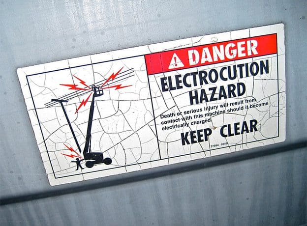
Figure 1. Electric shock danger sign
The lower body resistance, the greater the potential electric shock hazard. Body resistance can be divided into external ( skin resistance) and internal ( body tissues and blood stream resistance). Resistance to the flow of electricity is measured in ohms and varies widely. It is determined by three factors: the nature of the substance itself, the length and cross-sectional area (size) of the substance, and the temperature of the substance.Some substances, such as metals, offer very little resistance to the flow of electric current and are called conductors. Other substances, such as bakelite, porcelain, pottery, and dry wood, offer such a high resistance that they can be used to prevent the flow of electric current and are called insulators. Dry wood has a high resistance, but when saturated with water its resistance drops to the point where it will readily conduct electricity. The same thing is true of human skin. When it is dry, skin has a fairly high resistance to electric current; but when it is moist, there is a radical drop in resistance. Pure water is a poor conductor, but small amounts of impurities, such as salt and acid (both of which are contained in perspiration), make it a ready conductor. When water is present either in the environment or on the skin, anyone working with electricity should exercise even more caution than they normally would. However, in a small number of instances, the consequence is death from cardiac arrest, or from ventricular fibrillation (where the heart muscle beats in a spasmodic and irregular fashion) or from respiratory arrest. The magnitude of the current is the applied voltage divided by the impedance of the body. 
The overall circuit impedance will comprise the body of the casualty and the other components in the shock circuit, including that of the power source and the interconnecting cables. For this reason, the voltage applied to the body, which is commonly known as the touch voltage, will often be lower than the source voltage. The impendance of the body is determined by the magnitude of the touch voltage ( there being an inverse relationship between impedance and voltage) and other factors, such as the wetness of the skin, cross-sectional area of contact with the conductors, and whether or not the skin is broken or penetrated by the conductors.


Sources :
Petruzella, Frank. (1995). Industrial Electronics. Mc Graw Hill.1-2